Complete Air Treatment for Reliable System Performance

Feature
- Full RangeComplete after-compression equipment including air receivers, dryers, filters, and cooling systems, available for both standard and high-pressure applications.
- OEM & Original OptionsFlexible choices between OEM and original brands to meet different budget and performance requirements.
- Flexible ConfigurationsMultiple system combinations designed to meet various air quality levels in compliance with ISO 8573-1 standards.
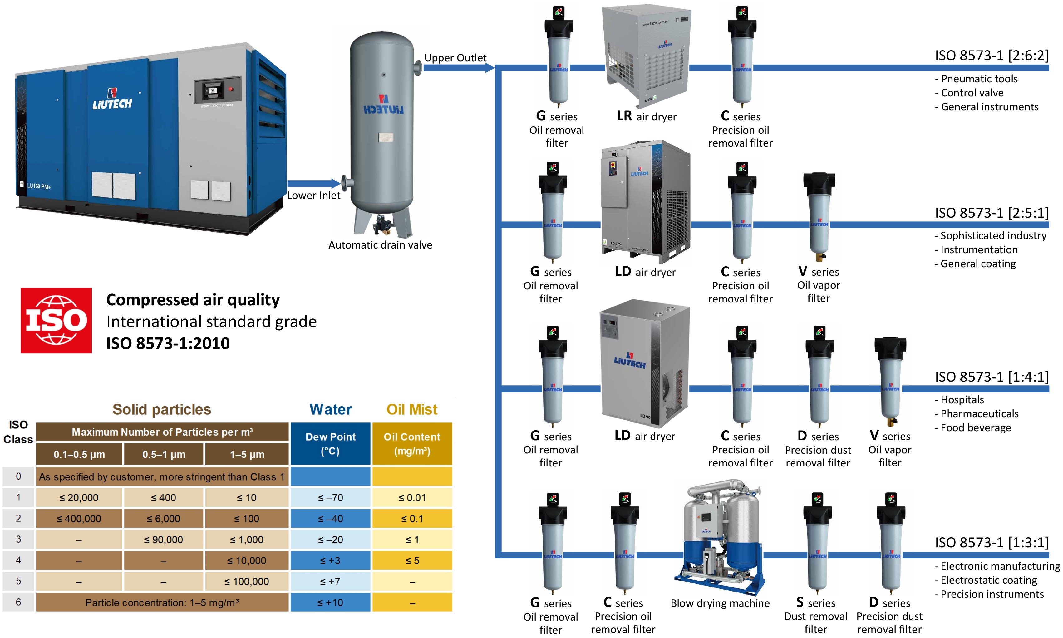
One Step Air Compression Station Configuration
Specific Model Parameter Table
LR10-260 Refrigerated Air Dryer Technical Data
| Model | FAD m3/min |
Dimensions LxWxH mm |
Installed Power W |
Weight Kg |
Refrigerant | Inlet/Outlet Size G |
Pressure Drop bar |
Power Supply V/Ph/Hz |
Condensate Drain Outlet mm |
| LR10 | 1 | 430X354X463 | 220 | 30 | R134a | G3/4" | 0.35 | 230/1/50 | 8 |
| LR13 | 1.3 | 548X400X615 | 360 | 36 | R134a | G3/4" | 0.35 | 230/1/50 | 8 |
| LR21 | 2.1 | 548X400X615 | 370 | 38 | R134a | G3/4" | 0.35 | 230/1/50 | 8 |
| LR40 | 4 | 600X520X750 | 700 | 56 | R410A | G1" | 0.35 | 230/1/50 | 8 |
| LR66 | 6.6 | 600X520X750 | 1050 | 58 | R410A | G1.5" | 0.35 | 230/1/50 | 8 |
| LR85 | 8.5 | 650X650X875 | 1100 | 75 | R410A | G1.5" | 0.35 | 230/1/50 | 8 |
| LR105 | 10.5 | 650X650X875 | 1150 | 79 | R410A | G2" | 0.35 | 230/1/50 | 8 |
| LR140 | 14 | 752X745X960 | 1400 | 102 | R410A | G2" | 0.35 | 230/1/50 | 8 |
| LR175 | 17.5 | 752X800X1020 | 1650 | 119 | R410A | G2" | 0.35 | 230/1/50 | 8 |
| LR220 | 22 | 927X795X1126 | 2650 | 168 | R410A | G2.5" | 0.35 | 230/1/50 | 8 |
| LR260 | 26 | 927X795X1126 | 2900 | 174 | R410A | G2.5" | 0.35 | 230/1/50 | 8 |
LR300-750W Refrigerated Air Dryer Technical Data
| Model | FAD m3/min |
Dimensions LxWxH mm |
Rated Power W |
Weight Kg |
Refrigerant | Inlet/Outlet Size DM |
Pressure Drop bar |
Power Supply V/Ph/Hz |
Cooling water interface size mm |
| LR300 | 30 | 1020X1000X1270 | 3663 | 300 | R410A | 80 | 0.30 | 230/1/50 | / |
| LR350 | 35 | 1020X1000X1270 | 3943 | 310 | R410A | 80 | 0.30 | 230/1/50 | / |
| LR450 | 45 | 1120X1150X1480 | 7218 | 350 | R410A | 100 | 0.30 | 400/3/50 | / |
| LR500 | 51 | 1120X1150X1480 | 7218 | 350 | R410A | 100 | 0.30 | 400/3/50 | / |
| LR600 | 60 | 1300X1100X1920 | 8530 | 500 | R410A | 150 | 0.30 | 400/3/50 | / |
| LR750 | 75 | 1450X1100X1920 | 10590 | 550 | R410A | 150 | 0.30 | 400/3/50 | / |
| LR300W | 30 | 1020X1000X1270 | 3481 | 310 | R410A | 80 | 0.30 | 230/1/50 | R 3/4" |
| LR350W | 35 | 1020X1000X1270 | 3481 | 310 | R410A | 80 | 0.30 | 230/1/50 | R 3/4" |
| LR450W | 45 | 1120X1150X1480 | 6272 | 350 | R410A | 100 | 0.30 | 400/3/50 | R 1" |
| LR500W | 51 | 1120X1150X1480 | 6272 | 500 | R410A | 100 | 0.30 | 400/3/50 | R 1" |
| LR600W | 60 | 1300X1100X1750 | 7056 | 500 | R410A | 150 | 0.30 | 400/3/50 | R 1" |
| LR750W | 75 | 1450X1100X1750 | 9116 | 550 | R410A | 150 | 0.30 | 400/3/50 | R 1 1/2" |
LD15-225 Refrigerated Air Dryer Technical Data
| Model | FAD m3/min |
Dimensions LxWxH mm |
Installed Power W |
Weight Kg |
Refrigerant | Inlet/Outlet Size G |
Pressure Drop bar |
Power Supply V/Ph/Hz |
Condensate Drain Outlet mm |
| LD10 | 1 | 354x439x445 | 228 | 30 | R134a | G3/4" | 0.3 | 230/1/50 | 8 |
| LD15 | 2 | 550x370x800 | 434 | 32 | R134a | G1" | 0.25 | 230/1/50 | 6 |
| LD21 | 2 | 550x370x800 | 434 | 36 | R134a | G1" | 0.15 | 230/1/50 | 6 |
| LD35 | 4 | 520x500x800 | 1165 | 60 | R410A | G1.5" | 0.14 | 230/1/50 | 6 |
| LD45 | 5 | 550x600x980 | 1240 | 68 | R410A | G1.5" | 0.1 | 230/1/50 | 6 |
| LD60 | 6 | 550x600x980 | 1240 | 75 | R410A | G2" | 0.1 | 230/1/50 | 6 |
| LD75 | 8 | 550x600x980 | 2058 | 85 | R410A | G2" | 0.1 | 230/1/50 | 6 |
| LD90 | 9 | 900x750x1000 | 2170 | 120 | R410A | G2" | 0.1 | 230/1/50 | 6 |
| LD115 | 12 | 1025x660x1120 | 1958 | 130 | R410A | G2.5" | 0.25 | 230/1/50 | 6 |
| LD150 | 15 | 1025x660x1120 | 2440 | 135 | R410A | G2.5" | 0.25 | 230/1/50 | 6 |
| LD175 | 18 | 1025x660x1120 | 2870 | 150 | R410A | G2.5" | 0.25 | 230/1/50 | 6 |
| LD225 | 23 | 1025x660x1120 | 3380 | 155 | R410A | G2.5" | 0.25 | 230/1/50 | 6 |
LD250(W)-2000(W) Refrigerated Air Dryer Technical Data
| Model | FAD m3/min |
Dimensions LxWxH mm |
Rated Power W |
Weight Kg |
Refrigerant | Inlet/Outlet Size G |
Pressure Dew point ℃ |
Power Supply V/Ph/Hz |
Condensate Drain Outlet mm |
Condensate water connection | Cooling Water Consumption L / min |
| LD250 | 25 | 1025x660x1120 | 3850 | 180 | R410A | G2.5" | 7 | 230/1/50 | 12 | — | — |
| LD350 | 35 | 1133x1000x1700 | 4860 | 325 | R410A | DN100 FL | 7 | 380/3/50 | 16 | — | — |
| LD450 | 45 | 1133x1000x1700 | 5626 | 350 | R410A | DN100 FL | 7 | 380/3/50 | 16 | — | — |
| LD500 | 50 | 1133x1000x1700 | 6293 | 350 | R410A | DN100 FL | 7 | 380/3/50 | 16 | — | — |
| LD600 | 60 | 1644x1000x1895 | 9171 | 550 | R410A | DN150 FL | 7 | 380/3/50 | 16 | — | — |
| LD750 | 75 | 1644x1000x1895 | 10069 | 600 | R410A | DN150 FL | 7 | 380/3/50 | 16 | — | — |
| LD1000 | 100 | 2100x1150x1900 | 14398 | 700 | R407C | DN150 FL | 10 | 380/3/50 | G1" | — | — |
| LD250W | 25 | 1025x660x1120 | 3430 | 205 | R410A | G2.5" | 7 | 230/1/50 | 12 | G3/4" | 41.7 |
| LD350W | 35 | 1133x1000x1550 | 4000 | 325 | R410A | DN100 FL | 7 | 380/3/50 | 16 | G1" | 50 |
| LD450W | 45 | 1133x1000x1550 | 4766 | 350 | R410A | DN100 FL | 7 | 380/3/50 | 16 | G1" | 63.3 |
| LD500W | 50 | 1133x1000x1550 | 5433 | 350 | R410A | DN100 FL | 7 | 380/3/50 | 16 | G1" | 75 |
| LD600W | 60 | 1644x1000x1750 | 7871 | 550 | R410A | DN150 FL | 7 | 380/3/50 | 16 | G1" | 83.3 |
| LD750W | 75 | 1644x1000x1750 | 8769 | 600 | R410A | DN150 FL | 7 | 380/3/50 | 16 | G1" | 108.3 |
| LD1000W | 100 | 2100x1150x1750 | 7936 | 700 | R407C | DN150 FL | 10 | 380/3/50 | G1" | DN40 FL | 141.7 |
| LD1250W | 125 | 2100x1150x1750 | 9866 | 750 | R407C | DN150 FL | 10 | 380/3/50 | G1" | DN50 FL | 175 |
| LD1500W | 150 | 2400x1150x1750 | 13697 | 850 | R407C | DN200 FL | 10 | 380/3/50 | G1" | DN50 FL | 208 |
| LD2000W | 200 | 2400x1150x1750 | 16517 | 950 | R407C | DN200 FL | 10 | 380/3/50 | G1" | DN65 FL | 275 |
LBD330-1800+P Blower Purge Adsorption Dryer
| Model | Rated FAD m3/min |
Dimensions LxWxH mm |
Weight Kg |
Connection Size | Blower Power KW |
Heater Power KW |
Avg. Regeneration Purge Consumption |
| LBD330+P | 19.8 | 1764*1024*2558 | 1190 | 3"(DN80) | 1.3 | 12 | 2% |
| LBD400+P | 24 | 1764*1024*2558 | 1300 | 3"(DN80) | 1.6 | 12 | 2% |
| LBD550+P | 33 | 1884*1024*2612 | 1620 | 3"(DN80) | 4 | 18 | 2% |
| LBD850+P | 51 | 2359*1175*2702 | 2600 | 4"(DN100) | 4 | 27 | 2% |
| LBD1100+P | 66 | 2472*1175*2681 | 3040 | 4"(DN100) | 7.5 | 36 | 2% |
| LBD1400+P | 84 | 2720*2199*2548 | 4200 | 6"(DN150) | 7.5 | 42 | 2% |
| LBD1800+P | 108 | 2793*2199*2548 | 4800 | 6"(DN150) | 7.5 | 52 | 2% |
LBD330-1800+ZP Series Blower Zero Purge Adsorption Dryer
| Model | Rated FAD m3/min |
Dimensions LxWxH mm |
Weight Kg |
Connection Size | Blower Power KW |
Heater Power KW |
Fan Power KW |
Cooling Water Consumption (L/s) |
| LBD330+ZP | 19.8 | 1764*1351*2558 | 1370 | 3"(DN80) | 2.2 | 12 | 0.44 | N/A |
| LBD400+ZP | 24 | 1764*1351*2558 | 1490 | 3"(DN80) | 4 | 18 | 0.44 | N/A |
| LBD550+ZP | 33 | 1884*1428*2612 | 1830 | 3"(DN80) | 7.5 | 24 | 0.44 | N/A |
| LBD850+ZP | 51 | 2359*1530*2702 | 2840 | 4"(DN100) | 7.5 | 36 | 1 | N/A |
| LBD1100+ZP | 66 | 2472*1530*2684 | 3340 | 4"(DN100) | 11 | 40 | 1 | N/A |
| LBD1400+ZP | 84 | 2720*2778*2548 | 4550 | 6"(DN150) | 15 | 52 | N/A | 1 |
| LBD1800+ZP | 108 | 2793*2825*2548 | 5150 | 6"(DN150) | 18.5 | 69 | N/A | 1.3 |
LHC30P-350P Series Compression Heat Purge Adsorption Dryer
| Model | Pressure Dew Point | Inlet FAD | Length | Width | Height | Weight | Connection Size | Installed Power | Cooling Water Consumption |
Inlet Temp | |
| ℃ | m3/min | mm | mm | mm | Kg | Air Connection | Cooling Water Connection | kW | m3/h | ℃ | |
| LHC30 P | -20 | 30 | 2700 | 1650 | 2610 | 2800 | 3"(DN80) | DN50 | 0.5 | 13 | 110-200 |
| LHC40 P | -20 | 40 | 2900 | 1800 | 2658 | 3000 | 4"(DN100) | DN65 | 0.5 | 20 | 110-200 |
| LHC50 P | -20 | 50 | 2900 | 1800 | 2695 | 3400 | 4"(DN100) | DN65 | 0.5 | 25 | 110-200 |
| LHC60 P | -20 | 60 | 3200 | 1800 | 2900 | 3800 | 5"(DN125) | DN80 | 0.5 | 30 | 110-200 |
| LHC80 P | -20 | 80 | 3500 | 1900 | 2904 | 4400 | 5"(DN125) | DN80 | 0.5 | 40 | 110-200 |
| LHC100 P | -20 | 100 | 3700 | 2100 | 2960 | 5200 | 6"(DN150) | DN100 | 0.5 | 53 | 110-200 |
| LHC120 P | -20 | 120 | 3900 | 2200 | 3071 | 6800 | 6"(DN150) | DN100 | 0.5 | 47 | 110-140 |
| LHC150 P | -20 | 150 | 4500 | 2630 | 3293 | 8300 | 8"(DN200) | DN125 | 0.5 | 59 | 110-140 |
| LHC180 P | -20 | 180 | 4500 | 2700 | 3340 | 10000 | 8"(DN200) | DN125 | 0.5 | 71 | 110-140 |
| LHC200 P | -20 | 200 | 4600 | 2800 | 3425 | 11100 | 8"(DN200) | DN125 | 0.5 | 78 | 110-140 |
| LHC220 P | -20 | 220 | 4600 | 2800 | 3483 | 12200 | 8"(DN200) | DN125 | 0.5 | 86 | 110-140 |
| LHC250 P | -20 | 250 | 5000 | 3200 | 3662 | 14500 | 10"(DN250) | DN150 | 0.5 | 98 | 110-140 |
| LHC300 P | -20 | 300 | 5400 | 3300 | 3760 | 16800 | 10"(DN250) | DN150 | 0.5 | 117 | 110-140 |
| LHC350 P | -20 | 350 | 5500 | 3400 | 3900 | 19500 | 12"(DN300) | DN200 | 0.5 | 137 | 110-140 |
LHC30I-350I Series Compression Heat Purge Adsorption Dryer
| Model | Pressure Dew Point | Inlet FAD | Length | Width | Height | Weight | Connection Size | Installed Power | Cooling Water Consumption |
Inlet Temp | |
| ℃ | m3/min | mm | mm | mm | Kg | Air Connection | Cooling Water Connection | kW | m3/h | ℃ | |
| LHC30 I | -40 | 30 | 2700 | 1650 | 2610 | 2850 | 3"(DN80) | DN50 | 12 | 13 | 110-200 |
| LHC40 I | -40 | 40 | 2900 | 1800 | 2658 | 3100 | 4"(DN100) | DN65 | 15 | 20 | 110-200 |
| LHC50 I | -40 | 50 | 2900 | 1800 | 2695 | 3900 | 4"(DN100) | DN65 | 18 | 25 | 110-200 |
| LHC60 I | -40 | 60 | 3200 | 1800 | 2900 | 4300 | 5"(DN125) | DN80 | 22 | 30 | 110-200 |
| LHC80 I | -40 | 80 | 3500 | 1900 | 2904 | 4900 | 5"(DN125) | DN80 | 27 | 40 | 110-200 |
| LHC100 I | -40 | 100 | 3700 | 2100 | 3039 | 5700 | 6"(DN150) | DN100 | 36 | 53 | 110-200 |
| LHC120 I | -40 | 120 | 3900 | 2200 | 3071 | 7000 | 6"(DN150) | DN100 | 42 | 47 | 110-140 |
| LHC150 I | -40 | 150 | 4500 | 2630 | 3293 | 8500 | 8"(DN200) | DN125 | 54 | 59 | 110-140 |
| LHC180 I | -40 | 180 | 4500 | 2700 | 3340 | 10200 | 8"(DN200) | DN125 | 72 | 71 | 110-140 |
| LHC200 I | -40 | 200 | 4600 | 2800 | 3425 | 11400 | 8"(DN200) | DN125 | 72 | 78 | 110-140 |
| LHC220 I | -40 | 220 | 4600 | 2800 | 3483 | 12200 | 8"(DN200) | DN125 | 72 | 86 | 110-140 |
| LHC250 I | -40 | 250 | 5000 | 3200 | 3662 | 15000 | 10"(DN250) | DN150 | 96 | 98 | 110-140 |
| LHC300 I | -40 | 300 | 5400 | 3300 | 3760 | 17300 | 10"(DN250) | DN150 | 120 | 117 | 110-140 |
| LHC350 I | -40 | 350 | Consult Manufacturer | ||||||||
LHCZ30P-350P Series Compression Heat Zero Purge Adsorption Dryer
| Model | Pressure Dew Point | Inlet FAD | Length | Width | Height | Weight | Connection Size | Installed Power | Cooling Water Consumption |
Inlet Temp | |
| ℃ | m3/min | mm | mm | mm | Kg | Air Connection | Cooling Water Connection | kW | m3/h | ℃ | |
| LHCZ30P | 0~-20 | 30 | 3100 | 1900 | 2650 | 3400 | 3"(DN80) | DN50 | 0.5 | 30 | 110-200 |
| LHCZ40P | 0~-20 | 40 | 3400 | 2000 | 2700 | 4150 | 4"(DN100) | DN65 | 0.5 | 40 | 110-200 |
| LHCZ50P | 0~-20 | 50 | 3400 | 2000 | 2790 | 4400 | 4"(DN100) | DN65 | 0.5 | 50 | 110-200 |
| LHCZ60P | 0~-20 | 60 | 3600 | 2300 | 2922 | 5200 | 5"(DN125) | DN80 | 0.5 | 60 | 110-200 |
| LHCZ80P | 0~-20 | 80 | 4000 | 2400 | 2985 | 6300 | 5"(DN125) | DN80 | 0.5 | 80 | 110-200 |
| LHCZ100P | 0~-20 | 100 | 4300 | 2800 | 3037 | 7200 | 6"(DN150) | DN100 | 0.5 | 106 | 110-200 |
| LHCZ120P | 0~-20 | 120 | 4600 | 2800 | 3154 | 8800 | 6"(DN150) | DN100 | 0.5 | 94 | 110-140 |
| LHCZ150P | 0~-20 | 150 | 5200 | 3350 | 3407 | 12000 | 8"(DN200) | DN125 | 0.5 | 118 | 110-140 |
| LHCZ180P | 0~-20 | 180 | 5400 | 3350 | 3463 | 13200 | 8"(DN200) | DN125 | 0.5 | 142 | 110-140 |
| LHCZ200P | 0~-20 | 200 | 5500 | 3400 | 3535 | 15600 | 8"(DN200) | DN125 | 0.5 | 156 | 110-140 |
| LHCZ220P | 0~-20 | 220 | 5700 | 3400 | 3575 | 16500 | 8"(DN200) | DN125 | 0.5 | 170 | 110-140 |
| LHCZ250P | 0~-20 | 250 | 6000 | 3600 | 3814 | —— | 10"(DN250) | DN150 | 0.5 | 196 | 110-140 |
| LHCZ300P | 0~-20 | 300 | 6400 | 3650 | 3952 | —— | 10"(DN250) | DN150 | 0.5 | 234 | 110-140 |
| LHCZ350P | 0~-20 | 350 | 6600 | 4400 | 4120 | —— | 12"(DN300) | DN200 | 0.5 | 274 | 110-140 |
LHCZ30I-350I Series Compression Heat Zero Purge Adsorption Dryer
| Model | Pressure Dew Point | Inlet FAD | Length | Width | Height | Weight | Connection Size | Installed Power | Cooling Water Consumption |
Inlet Temp | |
| ℃ | m3/min | mm | mm | mm | Kg | Air Connection | Cooling Water Connection | kW | m3/h | ℃ | |
| LHCZ30I | -40 | 30 | 3100 | 1900 | 2650 | 3500 | 3"(DN80) | DN50 | 15 | 30 | 110-200 |
| LHCZ40I | -40 | 40 | 3400 | 2000 | 2760 | 4600 | 4"(DN100) | DN65 | 22 | 40 | 110-200 |
| LHCZ50I | -40 | 50 | 3400 | 2000 | 2850 | 4800 | 4"(DN100) | DN65 | 27 | 50 | 110-200 |
| LHCZ60I | -40 | 60 | 3600 | 2300 | 3020 | 5400 | 5"(DN125) | DN80 | 36 | 60 | 110-200 |
| LHCZ80I | -40 | 80 | 4000 | 2400 | 3083 | 6900 | 5"(DN125) | DN80 | 42 | 80 | 110-200 |
| LHCZ100I | -40 | 100 | 4600 | 2800 | 3160 | 7900 | 6"(DN150) | DN100 | 54 | 106 | 110-200 |
| LHCZ120I | -40 | 120 | 4600 | 2800 | 3201 | 9200 | 6"(DN150) | DN100 | 54 | 94 | 110-140 |
| LHCZ150I | -40 | 150 | 6200 | 3350 | 3407 | 12300 | 8"(DN200) | DN125 | 72 | 118 | 110-140 |
| LHCZ180I | -40 | 180 | 6400 | 3350 | 3463 | 13500 | 8"(DN200) | DN125 | 96 | 142 | 110-140 |
| LHCZ200I | -40 | 200 | 6500 | 3400 | 3535 | 16000 | 8"(DN200) | DN125 | 96 | 156 | 110-140 |
| LHCZ220I | -40 | 220 | 6700 | 3400 | 3575 | 17000 | 8"(DN200) | DN125 | 120 | 170 | 110-140 |
| LHCZ250I | -40 | 250 | 7300 | 3650 | 3814 | —— | 10"(DN250) | DN150 | 120 | 196 | 110-140 |
| LHCZ300I | -40 | 300 | 7400 | 3650 | 3925 | —— | 10"(DN250) | DN150 | 150 | 234 | 110-140 |
| LHCZ350I | -40 | 350 | Consult Manufacturer | ||||||||
LE10-750E Heated Adsorption Dryer Technical Data
| Model | FAD m3/min |
Dimensions LxWxH mm |
Inlet Connection mm |
Rated Power KW |
Machine Weight Kg |
Power Supply V/Ph/Hz |
| LE10E | 1.35 | 800X600X1400 | G1" | 0.5 | 142 | 220/1/50 |
| LE20E | 2.6 | 800X600X1455 | G1" | 1.2 | 175 | 220/1/50 |
| LE30E | 3.8 | 800X600X1480 | G1" | 1.2 | 215 | 220/1/50 |
| LE40E | 5.2 | 1000X650X1650 | G1-1/2" | 1.5 | 256 | 220/1/50 |
| LE50E | 7.2 | 1000X650X1800 | G1-1/2" | 2.5 | 301 | 220/1/50 |
| LE60E | 8.5 | 1000X650X1850 | G2" | 2.5 | 338 | 220/1/50 |
| LE75E | 11 | 1150X750X1900 | G2" | 4.0 | 443 | 380/3/50 |
| LE85E | 13.5 | 1150X750X1800 | G2" | 4.0 | 462 | 380/3/50 |
| LE100E | 15.2 | 1150X750X2000 | DN65 | 4.0 | 508 | 380/3/50 |
| LE125E | 18.5 | 1350X800X2020 | DN65 | 6.0 | 651 | 380/3/50 |
| LE150E | 22 | 1350X800X2070 | DN80 | 6.0 | 765 | 380/3/50 |
| LE175E | 25.5 | 1350X800X2200 | DN80 | 6.0 | 826 | 380/3/50 |
| LE185E | 28.5 | 1500X900X2190 | DN80 | 7.0 | 932 | 380/3/50 |
| LE200E | 30 | 1500X900X2300 | DN100 | 7.0 | 1080 | 380/3/50 |
| LE250E | 35 | 1500X900X2380 | DN100 | 8.0 | 1118 | 380/3/50 |
| LE300E | 45 | 1800X1000X2450 | DN125 | 12.0 | 1395 | 380/3/50 |
| LE350E | 55 | 1800X1000X2625 | DN125 | 15.0 | 1560 | 380/3/50 |
| LE400E | 65 | 2000X1100X2750 | DN125 | 18.0 | 2049 | 380/3/50 |
| LE500E | 75 | 2100X1200X2750 | DN150 | 18.0 | 2350 | 380/3/50 |
| LE600E | 85 | 2450X1350X2740 | DN150 | 27.0 | 2680 | 380/3/50 |
| LE750E | 110 | 2450X1500X2850 | DN150 | 36.0 | 3490 | 380/3/50 |
LA10-750E Heatless Adsorption Dryer Technical Data
| FAD m3/min |
Dimensions LxWxH mm |
Inlet Connection mm |
Rated Power KW |
Machine Weight Kg |
Power Supply V/Ph/Hz |
| 1.35 | 800X600X1400 | G1" | 0.1 | 125 | 220/1/50 |
| 2.6 | 800X600X1455 | G1" | 0.1 | 154 | 220/1/50 |
| 3.8 | 800X600X1480 | G1" | 0.1 | 199 | 220/1/50 |
| 5.2 | 1000X650X1650 | G1-1/2" | 0.1 | 240 | 220/1/50 |
| 7.2 | 1000X650X1800 | G1-1/2" | 0.2 | 275 | 220/1/50 |
| 8.5 | 1000X650X1850 | G2" | 0.2 | 317 | 220/1/50 |
| 11 | 1150X750X1900 | G2" | 0.2 | 412 | 220/1/50 |
| 13.5 | 1150X750X1800 | G2" | 0.2 | 441 | 220/1/50 |
| 15.2 | 1150X750X2000 | DN65 | 0.2 | 465 | 220/1/50 |
| 18.5 | 1350X800X2020 | DN65 | 0.2 | 608 | 220/1/50 |
| 22 | 1350X800X2070 | DN80 | 0.3 | 723 | 220/1/50 |
| 25.5 | 1350X800X2200 | DN80 | 0.3 | 781 | 220/1/50 |
| 28.5 | 1500X900X2190 | DN80 | 0.3 | 897 | 220/1/50 |
| 30 | 1500X900X2300 | DN100 | 0.3 | 1021 | 220/1/50 |
| 35 | 1500X900X2380 | DN100 | 0.3 | 1052 | 220/1/50 |
| 45 | 1800X1000X2450 | DN125 | 0.3 | 1300 | 220/1/50 |
| 55 | 1800X1000X2625 | DN125 | 0.3 | 1496 | 220/1/50 |
| 65 | 2000X1100X2750 | DN125 | 0.3 | 1965 | 220/1/50 |
| 75 | 2100X1200X2750 | DN150 | 0.3 | 2243 | 220/1/50 |
| 85 | 2450X1350X2740 | DN150 | 0.5 | 2509 | 220/1/50 |
| 110 | 2450X1500X2850 | DN150 | 0.5 | 3290 | 220/1/50 |
LF9-490 Series Filters Technical Data
| LF Series Filters Model | FAD | Dimensions | Connection Size | Weight | Configuration | |||||
| Oil Removal | Fine Oil Removal | Dust Removal | Fine Dust Removal |
m3/min | LxWxH mm | G | Kg | Differential Pressure Indicator |
Automatic Drain Valve |
Manual Ball Valve |
| LF9 FG | LF9 FC | LF9 FS | LF9 FD | 0.9 | 90X80X312 | 3/4" | 0.77 | Yes | Yes | No |
| LF18 FG | LF18 FC | LF18 FS | LF18 FD | 1.8 | 90X80X312 | 3/4" | 0.78 | Yes | Yes | No |
| LF25 FG | LF25 FC | LF25 FS | LF25 FD | 2.5 | 90X80X367 | 3/4" | 0.89 | Yes | Yes | No |
| LF35 FG | LF35 FC | LF35 FS | LF35 FD | 3.5 | 110X100X380 | 1" | 1.4 | Yes | Yes | No |
| LF60 FG | LF60 FC | LF60 FS | LF60 FD | 6 | 126X100X435 | 1 1/2" | 1.68 | Yes | Yes | No |
| LF105 FG | LF105 FC | LF105 FS | LF105 FD | 10.5 | 155X131X565 | 2" | 3.28 | Yes | Yes | No |
| LF140 FG | LF140 FC | LF140 FS | LF140 FD | 14 | 155X131X600 | 2" | 3.63 | Yes | Yes | No |
| LF175 FG | LF175 FC | LF175 FS | LF175 FD | 17.5 | 155X131X645 | 2" | 3.85 | Yes | Yes | No |
| LF260 FG | LF260 FC | LF260 FS | LF260 FD | 26 | 193X171X767 | 2 1/2" | 6.14 | Yes | Yes | No |
| LF380 FG | LF380 FC | LF380 FS | LF380 FD | 38 | 210X196X920 | 3" | 8.78 | Yes | Yes | No |
| LF490 FG | LF490 FC | LF490 FS | LF490 FD | 49 | 210X196X1090 | 3" | 10.33 | Yes | Yes | No |
LF9-490e Series Filters Technical Da
| LF e Series Filters Model | FAD | Dimensions | Connection Size | Weight | Configuration | ||||||
| Oil Removal | Fine Oil Removal | Oil Vapor | Dust Removal | Fine Dust Removal |
m3/min | LxWxH mm | G | Kg | Differential Pressure Indicator |
Automatic Drain Valve |
Manual Ball Valve |
| LF9e G | LF9e C | LF9e V | LF9e S | LF9e D | 0.9 | 90X80X237 | 3/4" | 0.77 | No | No | Yes |
| LF18e G | LF18e C | LF18e V | LF18e S | LF18e D | 1.8 | 90X80X237 | 3/4" | 0.78 | No | No | Yes |
| LF25e G | LF25e C | LF25e V | LF25e S | LF25e D | 2.5 | 90X80X292 | 3/4" | 0.89 | No | No | Yes |
| LF35e G | LF35e C | LF35e V | LF35e S | LF35e D | 3.5 | 110X100X305 | 1" | 1.4 | No | No | Yes |
| LF60e G | LF60e C | LF60e V | LF60e S | LF60e D | 6 | 126X100X360 | 1 1/2" | 1.68 | No | No | Yes |
| LF105e G | LF105e C | LF105e V | LF105e S | LF105e D | 10.5 | 155X131X465 | 2" | 3.28 | No | No | Yes |
| LF140e G | LF140e C | LF140e V | LF140e S | LF140e D | 14 | 155X131X500 | 2" | 3.63 | No | No | Yes |
| LF175e G | LF175e C | LF175e V | LF175e S | LF175e D | 17.5 | 155X131X545 | 2" | 3.85 | No | No | Yes |
| LF260e G | LF260e C | LF260e V | LF260e S | LF260e D | 26 | 193X171X617 | 2 1/2" | 6.14 | No | No | Yes |
| LF380e G | LF380e C | LF380e V | LF380e S | LF380e D | 38 | 210X196X720 | 3" | 8.78 | No | No | Yes |
| LF490e G | LF490e C | LF490e V | LF490e S | LF490e D | 49 | 210X196X890 | 3" | 10.33 | No | No | Yes |
Air Receiver Tank
| Working Pressure | Working Pressure | Working Pressure | Vessel Height | Inner Diameter | Inlet/Outlet Connection | Drain Connection |
| 8bar | 10bar | 13bar | mm | mm | ||
| C 0.3-8 | C 0.3-10 | 1685 | 500 | Internal Thread Rc1-1/2 | External Thread Rz1/2 | |
| C 0.6-8 | C 0.6-10 | C 0.6-13 | 1870 | 700 | Internal Thread Rc1-1/2 | External Thread Rz1/2 |
| C 1-8 | C 1-10 | C 1-13 | 2160 | 800 | Internal Thread Rc 2 | External Thread Rz3/4 |
| C1.5-8 | C1.5-10 | C1.5-13 | 2265 | 1000 | Internal Thread Rc 2 | External Thread Rz3/4 |
| C 2-8 | C 2-10 | C 2-13 | 2765 | 1000 | Internal Thread Rc 2 | External Thread Rz3/4 |
| C 0.6-8 | C 0.6-10 | C 0.6-13 | 1870 | 700 | FlangeDN65 | External Thread Rz3/4 |
| C 1-8 | C 1-10 | C 1-13 | 2160 | 800 | FlangeDN80 | External Thread Rz3/4 |
| C1.5-8 | C1.5-10 | C1.5-13 | 2265 | 1000 | FlangeDN80 | External Thread Rz3/4 |
| C 2-8 | C 2-10 | C 2-13 | 2765 | 1000 | FlangeDN80 | External Thread Rz3/4 |
| C 3-8 | C 3-10 | C 3-13 | 2550 | 1300 | FlangeDN80 | External Thread Rz3/4 |
| C 4-8 | C 4-10 | C 4-13 | 2985 | 1400 | FlangeDN80 | External Thread Rz3/4 |
| C 5-8 | C 5-10 | C 5-13 | 2885 | 1600 | FlangeDN100 | External Thread Rz 1" |
| C 6-8 | C 6-10 | C 6-13 | 3120 | 1650 | FlangeDN100 | External Thread Rz 1" |
| C 8-8 | C 8-10 | C 8-13 | 3265 | 1900 | FlangeDN150 | External Thread Rz 1" |
| C 10-8 | C 10-10 | C 10-13 | 4415 | 1800 | FlangeDN150 | External Thread Rz 1" |
| C 15-8 | C 15-10 | C 15-13 | 4475 | 2200 | FlangeDN150 | External Thread Rz 1" |
| C 20-8 | C 20-10 | C 20-13 | 4835 | 2400 | FlangeDN200 | External Thread Rz 1" |
| C 30-8 | C 30-10 | 6710 | 2500 | FlangeDN200 | External Thread Rz 1" | |
| C 40-8 | C 40-10 | 6310 | 3000 | FlangeDN200 | External Thread Rz 1" | |
| C 50-8 | C 50-10 | 7910 | 3000 | FlangeDN200 | External Thread Rz 1" |
LMD Zero Loss Intelligent Drain Trap Technical Data
| Model | LMD280 | LMD760 | LMD2600 | LMD5300 | LMD150L |
| Dimensions (mm) | 150X68X169 | 173X68X169 | 173X88X169 | 236X122X197 | 226X122X197 |
| Air Compressor FAD (m³/min) |
8 | 22 | 75 | 150 | 150 |
| Dryer FAD (m³/min) | 16 | 44 | 150 | 300 | 300 |
| Filter FAD (m³/min) | 80 | 220 | 750 | 1500 | 1500 |
| Inlet Connection | 2XG1/2" | 2XG1/2" | 2XG1/2" | G1/2" 2XG3/4" | G1/2" 2XG3/4" |
| Outlet Connection | G3/8" | G3/8" | G3/8" | G1/2" | G1/2" |
| Discharge Method | Solenoid Valve | Motorized Ball Valve |
|||
| Power Supply AC | 24V / 110V / 220V | ||||
| Working Pressure | 0.8bar ~ 16bar | ||||
| Protection Grade | IP65 | ||||
| Level Sight Glass Component |
Anodized Aluminum Anti-corrosion | ||||
LEB Condensate Separator Technical Data
| Model | FAD m3/min |
Water Outlet Connection |
Oil Outlet Connection |
Working Temperature | Max. Working Pressure |
Dimensions mm |
Weight kg |
| LEB80 | 8 | 3/4" | 1 " | 5℃-60℃ | 16bar | 580x260x860 | 28 |
| LEB160 | 16 | 3/4" | 1 " | 720x320x950 | 44 | ||
| LEB300 | 31 | 1 1/2" | 1 1/2" | 1050x450x1050 | 76 | ||
| LEB480 | 48 | 1 1/2" | 1 1/2" | 1220x550x1120 | 93 | ||
| LEB700 | 71 | 1 1/2" | 1 1/2" | 1500x750x1320 | 135 |
Spare Parts

Ask For A Quick Quote
If you are looking for more information on our services, or how we could potentially help, we would love to hear from you!

High Standard
Superior Quality
High Standard
Superior Quality
High Standard
Superior Quality